Understanding I and Q - The Foundation of Signal Processing
An introduction to in-phase and quadrature signals and why this representation is useful in digital communications and signal processing.
In-phase (I) and Quadrature (Q) representation is the standard method for representing complex waveforms in Digital Signal Processing (DSP). This method decomposes a signal into two orthogonal components, allowing for precise control over amplitude and phase.
Mathematical Foundation
A standard sinusoidal signal is defined by its amplitude , frequency , and phase :
Using the trigonometric identity , the expression is rewritten as:
From this, we define the Cartesian components:
- In-phase (I):
- Quadrature (Q):
The final composite signal is expressed as:
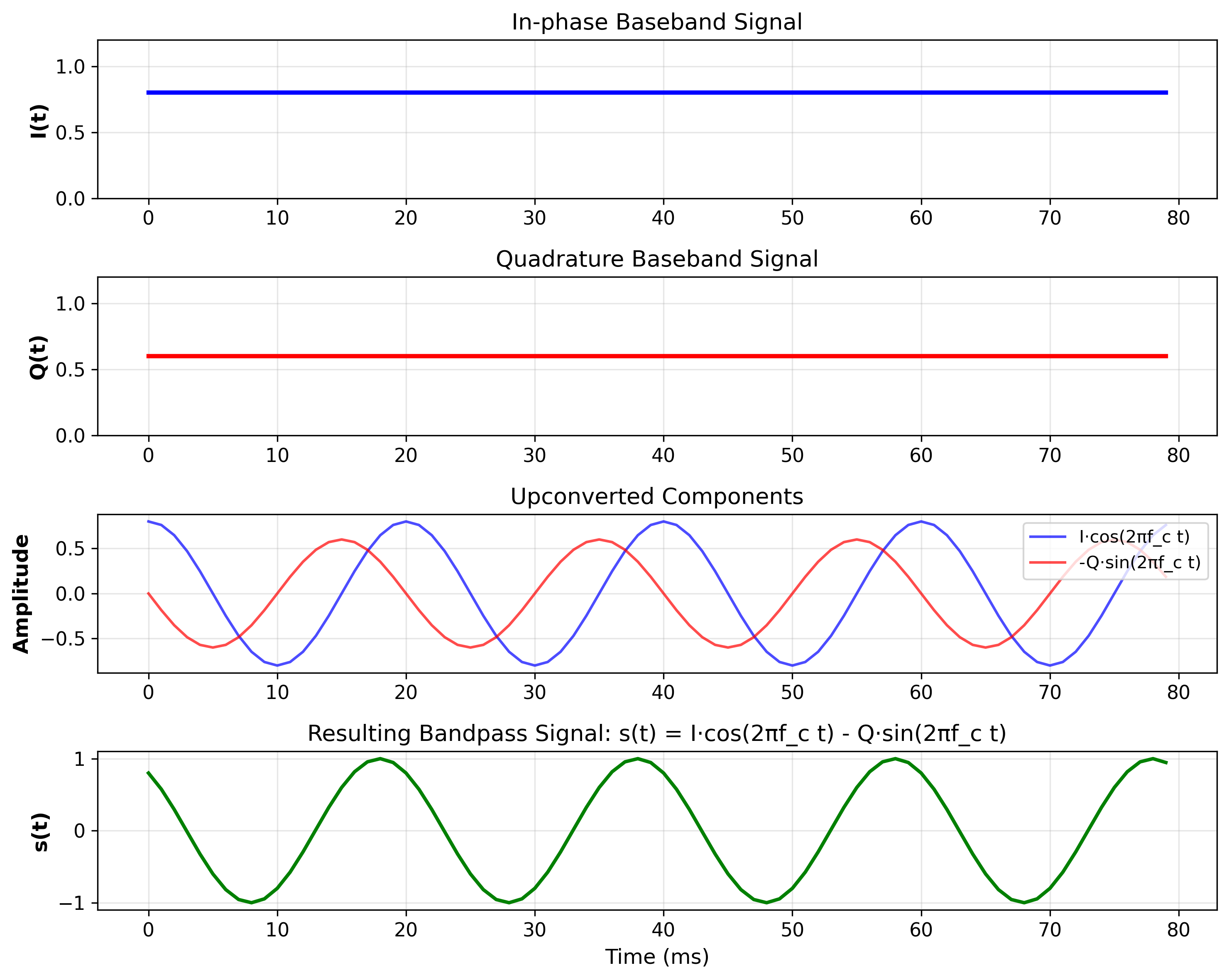
The below figure illustrates the synthesis of a bandpass signal from static In-phase (I) and Quadrature (Q) baseband components. The and DC levels scale a cosine and a negative sine carrier, respectively, creating two orthogonal waveforms. When summed, these components produce a single composite signal where the specific amplitude and phase are determined entirely by the relative magnitudes of and .
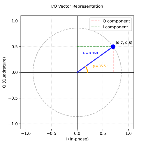
Orthogonality and the Complex Plane
The and components are mathematically orthogonal, meaning they are out of phase. In DSP, these are treated as a single complex number :
Where is the imaginary unit (). By utilizing Euler’s Formula (), we represent the signal in the complex exponential form:
Domain Conversions
Magnitude (A)
Phase ()
Why I/Q Representation Is Used
The I/Q framework provides several practical advantages:
-
Efficient modulation and demodulation
Complex baseband signals can be upconverted and downconverted using simple multiplications. -
Simplified filtering
Filtering at baseband avoids high-frequency analog filters. -
Robust digital processing
Phase, frequency offset, and amplitude variations can be estimated and corrected digitally. -
Natural fit for FFT-based systems
Most spectral analysis and communication algorithms operate on complex-valued data.